Mk 26 GMLS
History
The Mk 26 GMLS was fitted on board the Virginia class cruisers, Kidd class destroyers and Ticonderoga class cruisers. It was developed to replace the Mk 4 AWHS 1 on 1 in modernisation plans of the Spruance class destroyers. The Mk 26 had an relatively short time that it was installed on warships, as it was quicly replaced by the Mk 41 VLS.
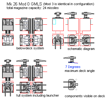
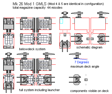
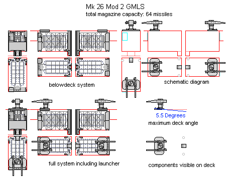
The Mk 26 could fire RUR-5 ASROC, RIM-66 Standard MR and RGM-84 Harpoon missiles. The magazine had an capacity of 24 missiles in the mod 0 and 3 installations, 44 in the mod 1,4 and 5 installations and 64 in the mod 2 installation. The magazine was build up from 2 independent rotary ready service rings (RSR), which could be lengthened into sections of 10 missiles (5 on each side) to create the larger magazines of the Mod 1,2,4 and 5. Each launcher arm was fed by one RSR. Missiles could be swapped between the ring and loaded/unloaded by the strikedown system at the back of the Mk 26 magazine. 2 plenum vents, in the aft corners of the magazine, led away gases and heat in case of an malfunctioning missile in the magazine. Nuclear interlocks were fitted on the ready service rings to allow the Mk 26 to fire nuclear depth charge ASROC.
The Mod 2 installation was never operationally installed but was proposed for DG/AEGIS and the various strike cruiser proposals. Mod 0 and 1 were fitted on the Virginia class, Mod 3 and 4 were installed on the Kidd class and mod 5 on the Ticonderoga class. Mod 3 and 4 were originally designated as Mod 0 and 1, however they had various engineering changes which reduced system cost and weight, and improved reliability, requiring an new designation. Mod 5 had further changes, adapting it to accommodate increased functionality for use with the AEGIS System.
Used on
- Virginia class (Mod 0 and Mod 1)
- Kidd class (Mod 3 and Mod 4)
- Ticonderoga class (Mod 5)
- CGN-9 AEGIS conversion proposal (Mod 2)
- CSGN Mk 2 (Mod 2)
- CSGN (Mod 2)
- CSGN (Mod 2)
- CSGN (Mod 2)
- CGN-42 (Mod 5?)
- DG/AEGIS (proposed)
- DG/AEGIS (proposed) (Mod 2)
- DG/AEGIS (proposed) (Mod 2)
Affiliated systems
Part description
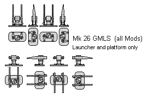
The various mods are drawn including the belowdeck installation. Full magazine views and schematic views are included. Different views of the launcher and the launcher in loading position are included in a separate image. Important to note are the deck angles allowed for the system, defined by the thickness of the platform and the height below the platform supports of the magazine itself. The plenum vents and strikedown system appear to be able to be adjusted in height, the RSR frame on the other hand cannot.


