You guys might have seen that I post very little ships lately. this is partially because I am crazy busy, but it is also about the fact that I have been working on this massive project.
The goal of project DX is to show the entire line of the DX-generation brought up to the latest standard, and with an background story when available. This includes all destroyer types leading to and derived from the Spruance hull, including for example DG/AEGIS, DX, DXG, Tico and Seahawk.
Why this project? about a year or more ago I did an update of the Spruance class here on the bucket. Only months later I did one of my best works, the perry. And looking back at the Spruance drawings, a ship which I like more, I did an pretty lousy job on them. So yeah, I could do better.
Now, with tons of research and hopefully some more skills and knowledge, I have started on this project. It is not my intention to redraw all vessels; the contrary, I try to change as little as possible to the existing drawings, and will not do any ships from scratch if an drawing already exists in the bucket, if I have not proven (with construction plans, all other is unacceptable) that they are so wrong that would be needed.
I did not include this project in my worklist because I always hope that others would do ships in the meantime, so I would not have to do them myself
while this thread will include both real designs and never build designs, and thus I have posted it in the general discussion section. I am not planning to upload these drawings separately onto the real design and never build sections of the forums (unless required?), but they will be in the upload sessions when they are ready.
----------------------------------------------------------------------------------------------------------------------------------------------------------------------------------------------------------------------------------------
Seahawk
Seahawk was a set of designs not directly related to the DX, but many of the systems designed for Seahawk were ultimately fitted on the Spruance. It is a concept so completely different than any other ship, that I could not help but start with these. The fact that these are chronologically the first steps to the DX project makes it a very good start as well.
Seahawk originated as a design for a very high speed destroyer escort/destroyer. Over time, the designation changed a few times from DE to DD, but I found DD the most fitting. The arnament was always similar of that of the then being designed Knox Class, with Sea Mauler, ASROC, a 5in gun and torpedo tubes.
The Seahawk program, SCB 239, originally called for a prototype to be funded under the FY 65 program, laid down in the last quarter of FY67 and commissioning in 1969. The fully integrated combat system would not be ready before 1971, so the prototype would be just a test platform for performance of the various systems and the hull instead of a fully operational warship.
The idea behind Seahawk was an improvement in ASW search speed to 25 knots. Endurance would thus rise from 20 knots to 25. The finalized Seahawk would be able to operate with this search speed in up to sea state 4. Much of its search performance would be improved by the new SQQ-20 sonar system and the new NTDS data handling system.
Initially, design effort was mostly concentrated on the choice of weapons and sensors. Detailed characteristics of October 1962 noted a cruising speed of 25 knots and a maximum (boost) speed of 30. Preliminary machinery studies were based on a 420 foot, 4175-ton hull, with 80000shp on 2 shafts and an endurance of 4500 nm at 20 knots. The alternative plants were CODAG and COGAG-E. In each case a maximum of 34 knots, and 30 with the VDS streamed, was expected.
The CODAG powerplant would offer a speed of 4500 nm at 20 knots but only 1900 at 25, where COGAG could promise 3100 at 25 knots and 4500 at 20.
After that, the Seahawk proposal went an entirely different direction. Admiral Anderson wanted an endurance of 5000 nm at 25 knots and a burst speed of 40 knots. This resulted in the ship becoming synonymous with the design of a 40 knots destroyer. A lot of the electronical equipment fell aside as being too ambitious.
There was no established requirement for a high speed destroyer, and the Seahawk project was far more concerned with reduced manning and with quiet operation at sonar speed. Results from pressure from yards resulted in the CNO shifting the Seahawk from an ASW system platform to an attempt to propel mostly existing systems at much increased speed.
The gas turbines ultimately selected would have been FT4s. the COGAG plants used 6 of them (2 propulsion, 4! Boost) the CODAG 4 FT4 and 4 diesels.
All this, resulted in the end as the following 5 designs (the specifications are in an excel file):
https://dl.dropboxusercontent.com/u/632 ... specs.xlsx
These 2 designs are the 2 which have graphical reference in US destroyers, for 3 others (the 2 steam variants of July 1963 and the COGAG variant of March 1964) I have only specifications. Any reference for these is welcome and will most likely be used to add to this project.
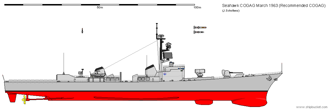
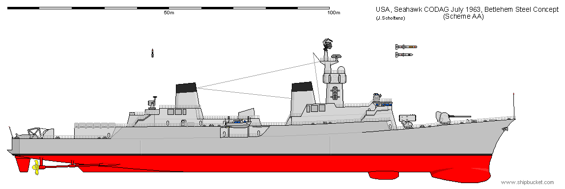
If we look at these ships, we can see how much is sacrificed for the large powerplant. This is what in the end has really killed Seahawk. The systems which were originally to be placed on board have at least inspired the new large ASW destroyer project, DX, which we now know to have ended in the Spruance Class.
----------------------------------------------------------------------------------------------------------------------------------------------------------------------------------------------------------------------------------------
Fast DE
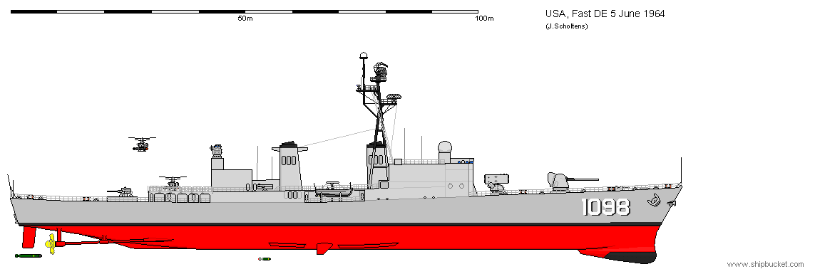
By 1964 the difference between Seahawk and the DE’s had become relatively small, and there was looked into an upgraded DE hull as alternative to the Seahawk. From this, a series of studies emerged.
The first one of these would have used an DDG-2 power plant in an enlarged DE-1052 hull. the SQS-26 would be supplemented by an new VDS, the SQS-35. There would be space reserved for the system that would end up to be BPDMS, but until that was ready an twin 3in/50 would be fitted. The result would have been close to Seahawk, and had with an price of 58 million for the first ship and 37 million for repeat ships, which was much more than that of DE 1052 class ships (20 million). This killed this design.
The displacement would have been 4247 tons light and 5578 tons full load.
L*B*T would have been 137,16 * 14,94 * 4,97 meters, resulting in an Cb of 0,55.
Range would have been 4500 at 20 knots, and the top speed would have been 30 knots. For that she required 70000 shp (52,2 MW)
----------------------------------------------------------------------------------------------------------------------------------------------------------------------------------------------------------------------------------------
DDG FY67
At a Buships meeting during the preliminary designs for the DX and DXG (1986-1987), it was proposed to authorize the DDG FY67 to test a variety of DX/DXG components. These components were Tartar D, gas turbines and modular command & control spaces.
DDG FY67 was supposed to be an updated, long range follow-on design for the earlier DDG’s. Various powerplants were proposed; COSAG, COGAG and 1200psi steam plant. COSAG was rejected on the grounds of both maintenance (of the steam plant) and specialised personnel (gas turbine). SCB chose for a COGAG powerplant, but on 12 august 1965 the CNO opted for the steam plant. Buships suggested a 600psi plant to avoid maintenance problems. This drove up the ships size.
The advantages of gas turbines were clear though, and the final design went back to COGAG. This design was 160 meters long on the waterline, 168.4m long OA, had a beam of 18.29m and a draft of 5.85m. Displacement was 6272 (light ship) and 8586 (full load). She would have had a crew of 360 and a 63,4MW powerplant. This would give her a range of 7000nm at 20 knots. Interesting was her double decked machinery layout: the base load turbines were on the main deck, electrically coupled to the gearboxes in the hull. This was done so the base load turbines could be replaced by regenerative cycle ones without the need for a drydock. This setup also made the ship extremely quiet, as the only systems running in the hull would be the gearbox and the electrical engine.
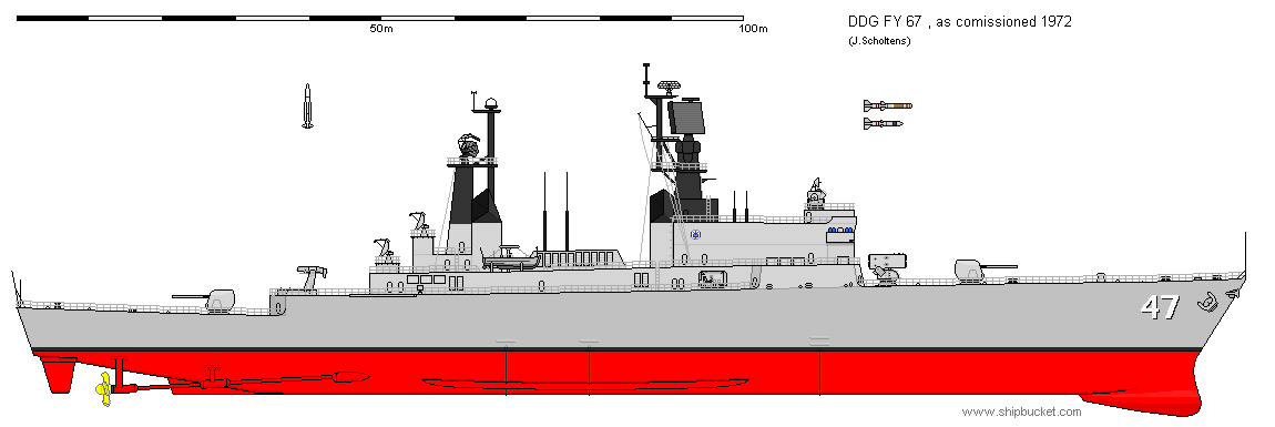
What killed this design was not that it was a bad design, but the sentiment that any new ship over 7000 tons should have nuclear power. As a result, the DDG FY67 was not ordered: instead, congress bought 2 nuclear DLG’s, the California class.
The DDG FY68 program thus went for weight reduction, but in the end the result was that these designs were replaced by a number of DXG’s, and by the ASMS plans (which ended up becoming AEGIS). More about that later on.
----------------------------------------------------------------------------------------------------------------------------------------------------------------------------------------------------------------------------------------
DE FY68
there were some additional DE's planned to be authorised in FY 68. suggestions were made to make these ships an modified design, closer to fleet speed and with the data handling systems of seahawk.
I have here included the designs of July and August 1966, which are described in US Destroyers. both would have had 40000 shp, and would have been armed with (quite interesting) 127/54 RF mounts, pointing at the heavy Mk 42 instead of the LW mount then in development. this was done for 360 degrees AA cover, as the aft mount would have been replaced by an point defence missile system when this became available.
the July proposal was considered too big, as it was pushed towards an heavy destroyer/light cruiser in size. it would have had 3 boilers and 2 shafts based on an pressure of 600 psi. this drove up the size to even larger then the earlier proposals, even while their top speed would have been faster.
when drawing this proposal out, I ended up taking more parts and ideas from the DX baseline proposals than of the earlier DE's, because these were more suitable. the ship thus seems to be an good step towards DX, although it is unrelated in all but role in reality, and was rejected.
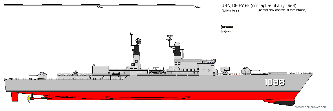
one way out of this large size problem would have been to use an COGAG powerplant consisting of 2 FT4 gas turbines fitted to an single shaft. the coupling would be electrical to enable reverse.
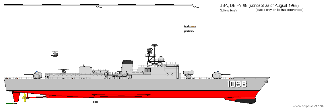
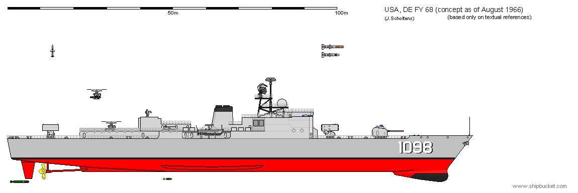
the plan was to use an common hull and machinery for both an DE and DD (I would list the DD more as DEG but I will follow the way Friedman noted them) DASH, the VDS and the long TT in the stern were deleted and replaced by an austere tartar launcher (I supposed this could only mean Mk 22)
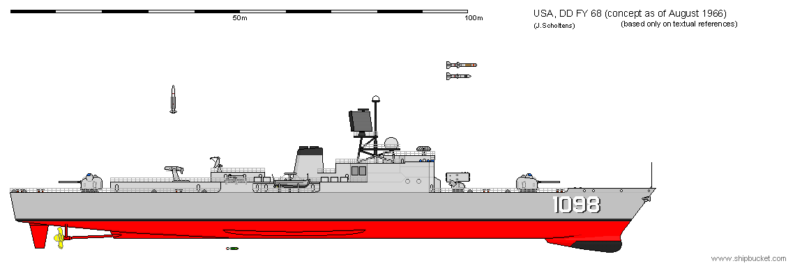
Friedman notes that this common hull idea must have influenced the DX/DXG project, which was just getting under way in the fall of 1966.
in the end, the FY 68 DEs were cancelled, and there is no evidence that they would have differed significantly from the FY64-67 DEs, but almost certainly these studies have influenced the weapons fit and possibly layout of the DX/DXG.
----------------------------------------------------------------------------------------------------------------------------------------------------------------------------------------------------------------------------------------
DX/DXG
By 1966 it became apparent that the many of the missile ships converted from World War II cruisers would soon have to be retired. Therefore a new class of missile ships was required. at the same time the end of the DE 1052 program was in sight and a new (ASW) escort ship program had to be restarted. for 1968 the secretary of defence requested a contract definition for a new guided missile destroyer or escort, designated DXG, and also for a new ASW escort, DX. It was observed that ‘joint funding will permit investigation of the desirability of various degrees of commonality between the DX and the DXG’. From the beginning, the new program was seen as an major fleet escort, which those days meant missile escort.
The DXGs had to replace the missile cruisers and partially the DEGs, which were seen as marginal at best.
The DX was seen as an ship propelled by the new gas turbine. At this point the DX was seen as little more than a DE, hardly fast enough for carrier operations. However, in the fall of 1967 it was suggested that there were enough DE types, but there was a need for 30-knot ASW ships with better guns than the DE.
DX and DXG would at this point not share more than some systems, but would complement each other in the carrier escort fleet. There were less AA launchers required then ASW screen ships, so some fast DX ships could replace some of the current missile ships in the formation.
The 1966 OSD concept called for 18 DXGs and 75 DXs in FY 69-74
One of the options was for the 2 classes to share identical hulls, and differ only in weapon systems. This would maximize standardisation and would take benefit from the economics of large scale production. However, if the DX would grow to such sizes that it might still be preferable to keep the classes separate. A common hull would facilitate modular construction though, in which the systems would be nearly ready to operate when installed in the hull, making it easier to build and to modernise the ships in later years.
The procurement of these vessels would be on a total package basis, with a single private contractor creating the design and then building all units.
The ships were to be designed with modernisation in mind, so there were margins for future growth ready in the design. This was something entirely new in warship design back then. Such an modernisation would occur about every 10 years.
After it was decided DX and DXG would have the hull in common, was conversion. In case a thread would arise in which DDGs were more valuable than DDs, the DXs were to be converted to an ‘AAW Area Defence Escort’, in other words a frigate.
On 23 September 1966 a special study group called for a five year program of 18 DXGs and 85 DXs to replace 250 elderly escorts. The first units would have to be ready in 1973. In this study was the DDG FY67, mentioned above, which was the latest design available, and the DX would be an ‘deconverted’ DXG, reduced to DE 1052 standard of weapons.
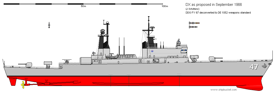
In June 1967 a new study was done which looked at what capability was needed. Out of this was concluded that there were to be ASW/shore support destroyer (DX 2) and an AAW/ASW DDG (DXG 1) respectively 40 and 20 were seen as needed.
The requirements for the DX/DXG were finally set in January 1968, calling for:
- CVA escort
- two guns for fire support
- sustained speed of 30 knots in sea state 4
- 6000 nm endurance
- ASROC
- the conversion from DX to DXG had to be simple and economical
- DX would have helicopter facilities, DXG only a platform
----------------------------------------------------------------------------------------------------------------------------------------------------------------------------------------------------------------------------------------
DX/DXG Notional ships
The procedure followed by the navy was to sketch a series of notional ships (baseline designs) that would test the feasibility of the proposed performance standards. Only those standards would be transmitted to the bidders in the form of requirements. These studies indicated quite early that the DX would be an exceptionally large destroyer.
The reason for this is not hard to find. Although the DX had roughly the DE arnament, it had to be converted to be a DDG, which was by now very close to an frigate. That meant the DX would in size be close to an DLG. In addition, the combat system fitted in DX was to be the one developed for Seahawk, which would drive up cost without providing an obvious increase in weapons or firepower. Current experience also learns that modular construction adds size as each space has to be slightly bigger than what actually fits in.
Had the systems not driven size though, the outcome would still be an very big ship. This was because of the speed requirement in sea state 4, which could not have been done by an much shorter ship.
Still, the greatest driver for size would be the conversion to DXG. At first this entailed an quite austere DDG, replacing the Mk 16 ASROC and one 5in/54 by an single arm launcher for both tartar /ASROC launcher (Friedman notes that even the Mk 22 was suggested, but this, as is known, cannot fire ASROC) it was estimated by NAVSEC that such a ship could be had on about 5700 tons, light ship.
These designs are following the drawings by A.D. Baker III but had no measurements given. These are thus scaled by their various parts and compared with the final DX designs for reference. They might be off, but they should be pretty close.
Notional ship B (ASW) shows very well how ‘empty’ the DX was proposed to be. Interesting is that SPS-49 was supposed to be placed (Spruance had SPS-40), Mk 25 sea sparrow launcher (Spruance had Mk 29 NSSM) and the remote optical sight of the Mk 86 FCS (instead of the SPG-60 with the optical sight on it) the ship is also steam driven.

Notional ship B (AAW) seems to not fill the requirement for the DXG, as it no longer has a helideck. However, the empty stern might make helicopter operation possible. This drawing was also the only one having a ECM system specified, named ‘Shortstop’

This design is the most interesting. It is not mentioned in the text. The ASMS system fitted on it is, according to Friedman, in this setup only possible to be fitted on a DLG(N) and this design seems to prove otherwise. The ASMS system was supposed to be fitted inside 2 deckhouses which would be installed as late as possible in the construction process. Only the CIC equipment would stay out of these deckhouses.
On the ship is also an unknown launcher, and an unknown missile which I have represented by Tartar here. It is unknown if at this stage the missile would be developed new or based on 3T, as was done in AEGIS. The radar on the aft mack is also unknown
It is interesting to see that this ship is the only ship with a different hull then the others. Even the DX 2 (shown underneath this one), while not part of the same series, is represented by the same hull as the ones above.

Notional ship DX2 is similar to notional ship B (ASW) except that it uses the common launcher, also known as Mk 26. Note that the forward gun is not the Mk 71 but the 175/60 gun developed for the LFS (fire support ship) most likely this ship was part of another series, as I suppose there would have been an DXG with the Mk 26, but I have found no references for this and thus have no drawing of these designs.

The notional designs were not shown to the yards, but were used to set a benchmark for the yards. the designs the yards supplied would be judged by comparing them with these.
Littom won the contest, with the 3-gas turbine design shown below. Bath Iron Works on the other hand lost, but it is interesting to compare what they came up with.

----------------------------------------------------------------------------------------------------------------------------------------------------------------------------------------------------------------------------------------
DD 963 Spruance Class: real designs
the actual result of this project, the DX spruance class. this is the first ship drawn in the project that was actually build.
I will finish the background storyline of it when I do the direct predecessors, which are still missing above.
the first ship of the line, the DD-963 Spruance.
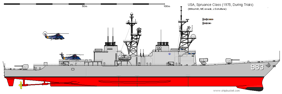
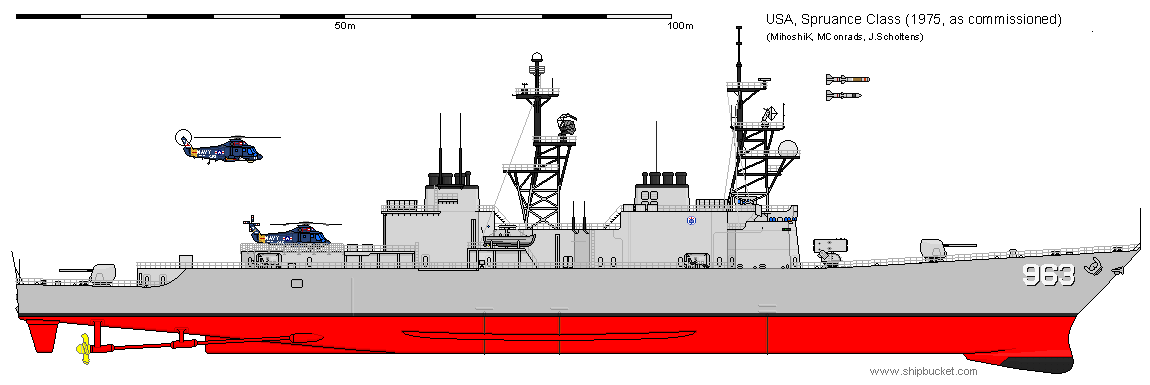
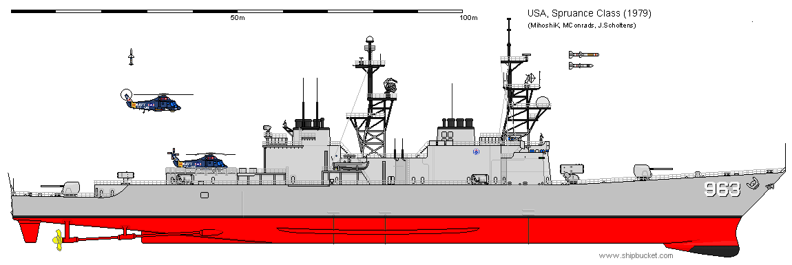
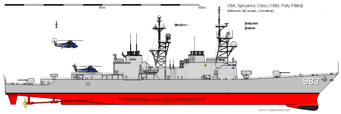
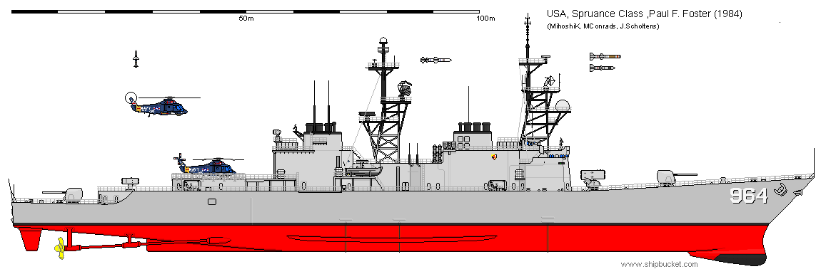
The DD-963 did not receive Mk 23 TAS before it's VLS update, the DD-964 however did.
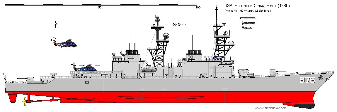
DD-976 was used for the testing of the armoured box launcher in 1980, and from this ship the first tomahawks were fired. Other spruances received the ABL's as well and used them operationally, following the same arrangement.
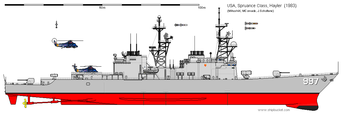
DD-997 was the Spruance class that was build last, even after the Kidd class. Possibly for that reason, she has some differences from the other ships, although not as many as would have been there when she was authorised as DDH. More about that in the never build section.
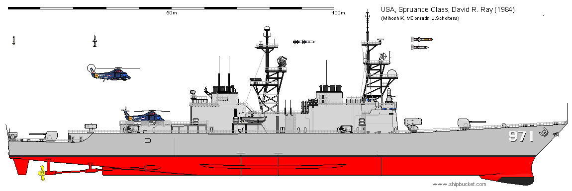
DD-971 was given an Mk 49 RAM when she was equipped with phalanx in 1984. The launcher was removed again after testing.
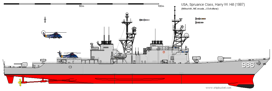
DD-986 Harry W. Hill was the only Spruance class destroyer which was never fitted with the tomahawk. She was only lightly modified over the years. As build, she can be represented by the standard Spruance class, but when other ships were completely converted she received only minor updates. this vessel also never received Mk 23 TAS and the SH-60 hangar.
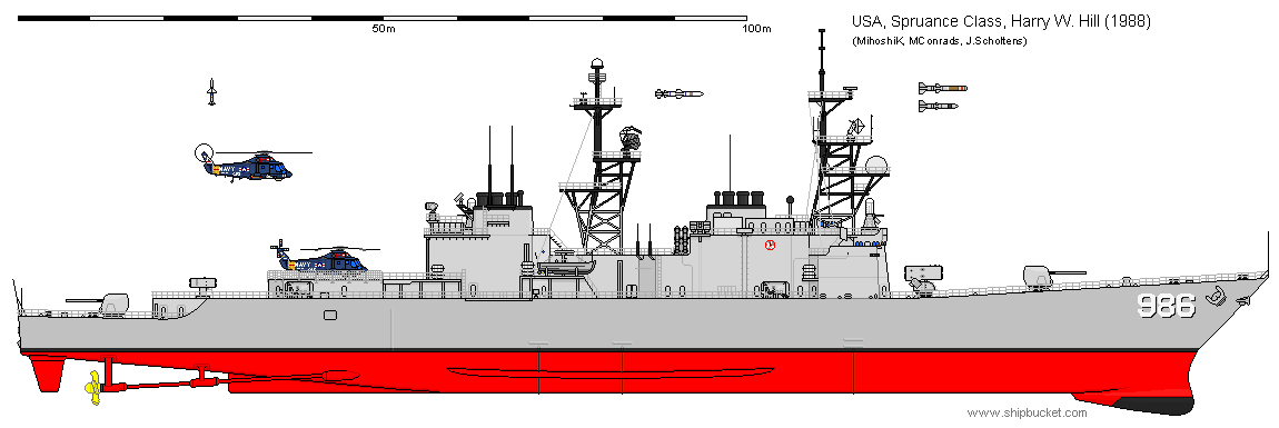
In 1988 she received the phalanx CIWS.
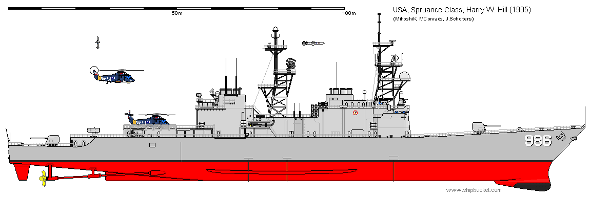
Around 1995 her funnels were coloured grey, her forward replenishment bay was closed up and the ASROC launcher was removed. She stayed this way until decommissioned in 1998
----------------------------------------------------------------------------------------------------------------------------------------------------------------------------------------------------------------------------------------
DD 963 Spruance Class: never build designs
The initial design for what became the Spruance class was slightly different from what we are all familiar with. The original design by Litton was submitted in April 1969, and showed an different arrangement of funnels, air intakes and masts.
Notable are also the different pilothouse layout, ECM system and the decoy launchers on the stern.
The designs goal of maximising the profile similar to how the Europeans did this, is clearly visible in the rounded funnels and the high superstructure.
As part of the same design series, the DXG conversion of these ships was already part of the design. For that reason, I include here the derived design for the DXG conversion.
to lower the fuel consumption of the gas turbines when the ship required only low power, littom proposed to attach a large electric motor-generator to the main reduction gear on each propeller shaft of their design proposal. at cruising speeds, one gas turbine would drive the propeller and electrical power to the other propeller shaft. this would give half the power of the gas turbine to each shaft. an mechanical connection between the 2 shafts was impossible due to the shafts not being in the same angle with the keel. the shaft of the forward engine room was longer and lay at a shallower angle then the one from the aft engine room. in their design littom proposed to fit only 3 gas turbines in the ship: 2 in the aft engine room and one forward. this design would reach 30 knots on 3 gas turbines.
this design was chosen in the end, but without the electrical cross-coupling and with 4 LM2500 gas turbines. because of this, the spruance class was slightly larger and faster then required.
the ship with 3 gas turbines would have been exactly the same as the ship that was build, but for the intakes and uptakes of the forward engine room. the intake deckhouse would have been slightly smaller, but not much because it was also used as the gas turbine removal hatch. the uptake could have 2 shapes: 3 pipes behind each other, the 3 that were next to it being removed, or the 3 forward/aft pipes being removed. I chose to remove the forward 3, not for any technical reason (it is even slightly more logical to have the 3 in line due to the exhaust dampeners construction) but because otherwise it would be nearly invisible that the ship was changed.
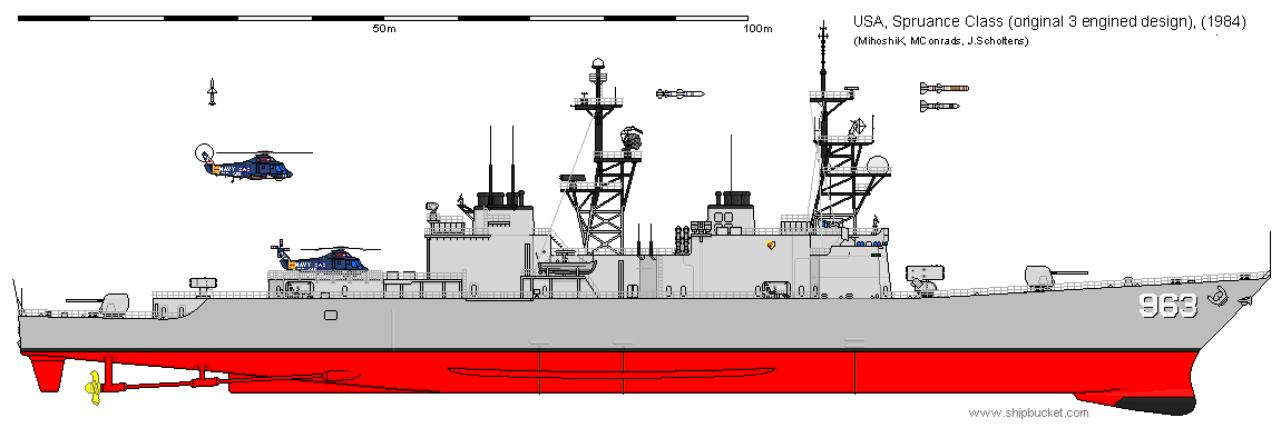
the spruance design was defined by it's ability to get from the basic ship (spruance 1979) into an more capable ship.
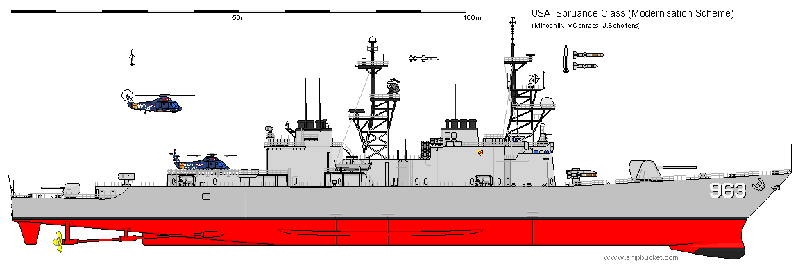
the first step of this was the modernisation, which replaced the Mk 4 AWHS with the Mk 26 Mod 0 launcher. this removed no magazine space, but added the capability to launch AA missiles. the forward Mk 45 main gun was replaced by an Mk 71 8in gun. CIWS and Harpoons would be added, as was done on the real ships.
the second step would be to convert the modernised DX to an AAW combatant, basically resulting in the DXG. an Mk 26 Mod 1 launcher replaced the Mk 29 aft, the SPS-40B would have been replaced with an SPS-48 and the fire control system updated (new gun fire control system, and the addition of SPG-51 directors)
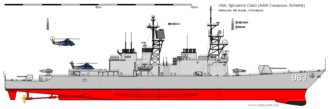
it is interesting to note the difference between these ships, designed for the US navy, and the Kidd class.
this last drawing is again based purely on textual sources, so the exact placement of the directors and affiliated superstructure is more based on the Kidd then on the real plans for these ships. that said, I think I got quite close to how they would have looked if converted along these plans.
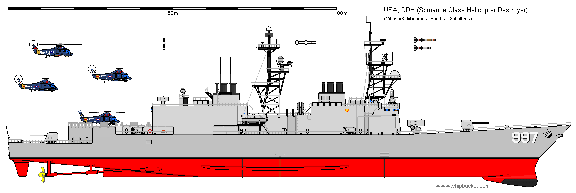
in 1979 one additional ship was ordered. this ship, DDH-997, would have been an helicopter destroyer, capable of operating 2 sea kings or 4 SH-2 or SH-60. the Navy did not really want this ship, and the changes would result in a ship that would be costlier to construct. this cost would be justified if the ship was to enter series production, but it was not for a single ship. in the end, the hayler was only slightly modified compared to the rest of her class.
----------------------------------------------------------------------------------------------------------------------------------------------------------------------------------------------------------------------------------------
'Warships should look warlike' Spruances.
in june 1979 Lt. John Roach USNR wrote an article in USNIP called "Warships should look warlike". it was more or less an complaint to the USN that the spruances were big boxes (as were the patrol frigates then under construction) and looked underarmed and powerless at the time. especially when comparing with the russian and, to some extend, british vessels, which looked more like warships to his opinion.
the Lt added a few sketches to his article, which focused on a lower profile and more prominent display of weapons. the internal volume was kept in similar levels as the real ship, but the functionality was completely ignored. for example, the DXG conversion was most likely no longer possible on these designs.
the first modification had only modest changes, mostly the lowering of the heli hangar and the heightening of the ASROC location, an remodel of the funnels and an knuckle in the hull.
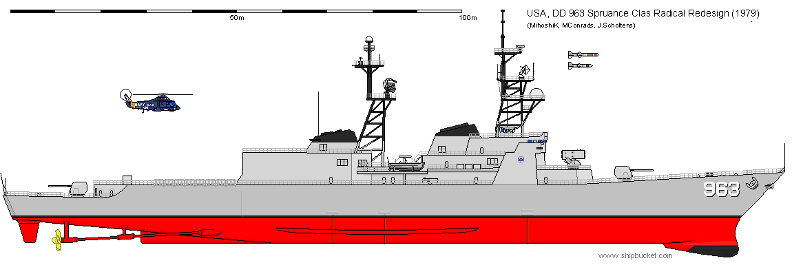
the second modification was more radical, and moved the ASROC aft and both guns forward. the mast was remodelled to create an sweep forward. the hull was kept the same from the first conversion [this drawing is made by Scifibug some time ago, I only swapped some parts so I do not receive credit for this drawing, hence why Scifibugs name is still at the end of the credit line]
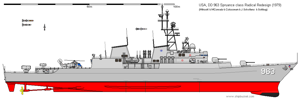
I would like to expand this text but I sadly don't have the article this was based on in my posession. if anybody has them, I would love to read it and expand and improve this text where needed.
----------------------------------------------------------------------------------------------------------------------------------------------------------------------------------------------------------------------------------------
DXN LWNP - the Nuclear powered Spruance class
In the LWNP paper which has floated quite a lot around here on the forums, there is an section named 'Application to a High Performance Displacement Ship.' After some research I found out that this ship was an Spruance class.
I came to this conclusion because the hull shape, powerplant, GM value and tonnages matched perfectly, and because this was the main surface combatant then (1977) under production in the US. The paper only gives the internal arrangement of the forward engine room and some numbers, but I have tried to offer an topside design matching these engines.
I have chosen the USS thorn as the ship that would take these, as she was laid down shortly after the paper was released. Logically, it might also have been the Hayler, as that was an modified design anyways and thus made more sense for an changed powerplant vessel, but as I wanted to look into all differences from the main Spruance before going from Hayler, the thorn was another logical choice.
the ship would have the current sizes (only those changed from the Spruance and known are given, with the Spruance sizes in brackets behind them) all measurements are in meters or SI units unless stated otherwise
commissioning year: 1980 (1975)
draft: 6,41 (6,30)
displacement: 9077 (8881)
hull steel weight: 3320 (3192)
Propulsion plant weight: 1712 (773)
GM: 1,29 (1,43)
installed power: 73,6MW (63,2MW)
powerplant: 4 Westinghouse LWNP, 18,4MW each (4 GE LM2500, 15,8MW each)
range @ 20 knots: unlimited (6000 NM)
range @ top speed: unlimited (3300 NM)
top speed: 32,3 knots (32,5 knots)
from these specifications, I have drawn this series of drawings. (note, these will not be in the first post, but only in the thread, as they will be treated separately from project DX.)
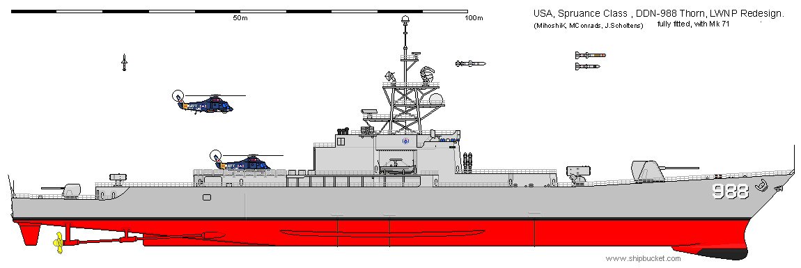
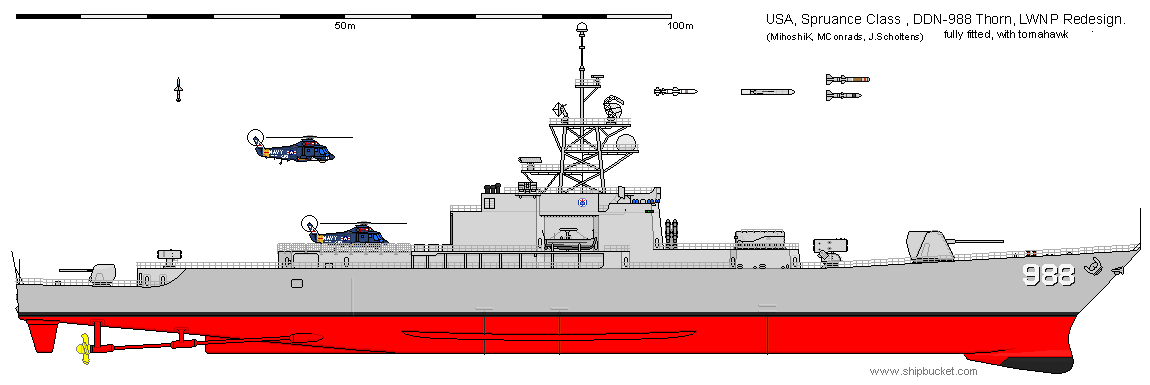
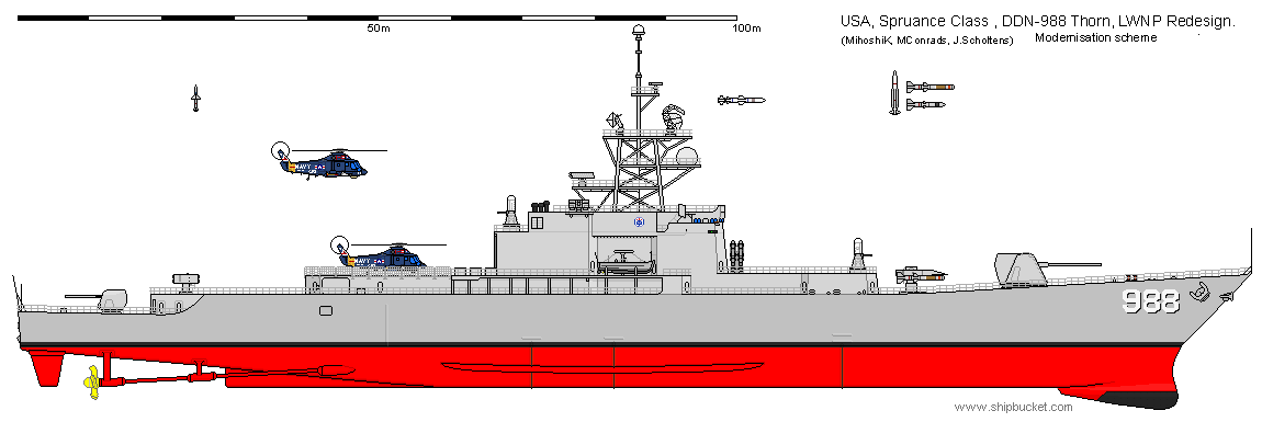
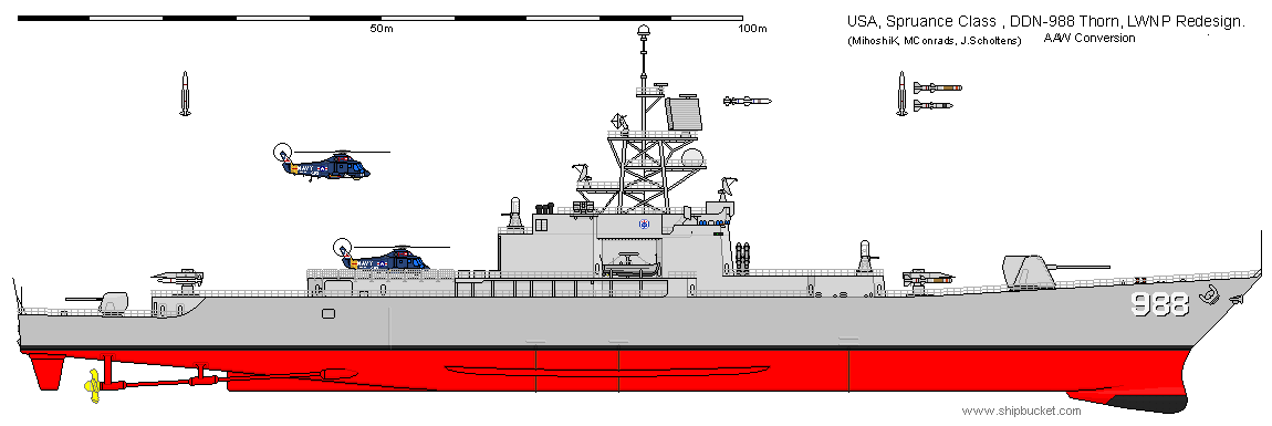
there are 2 basic frames: the 'refit' in which the basic spruance is kept as much as possible, and the 'redesign' in which everything on top of the main deck is reconfigured to provide easier removal of the LWNP and optimal usage of the available space in the superstructure that remains.
basic spruance refit:
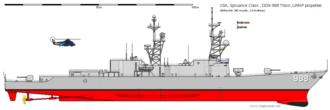
The topside arrangement is changed only by removing funnels and intakes, apart from the ones for the gas turbine generators still on board
Note that the 'unlimited' above is operational unlimited, the reactor and the gas turbine generators still need fuel.
The superstructure shape is slightly modified as well: in the front structure the space previously taken by the uptakes and intakes is mostly incorporated in the superstructure, keeping intact an shaft for removal (for maintenance and/or refuelling) of the reactor. For the front engine room, this shaft runs until one deck above the main deck, after which the LWNP is moved sideways until it can be craned out. This arrangement makes it possible for the superstructure to be one deck lower.
The aft engine room has the shaft running directly trough the main deck. In rebuild, the shaft would most likely be taken one deck higher into the full beam hangar, but as build I have just removed the part of the superstructure that had the in- and uptakes in it.
design with optimised superstructure arrangement for the LWNP shafts, as build
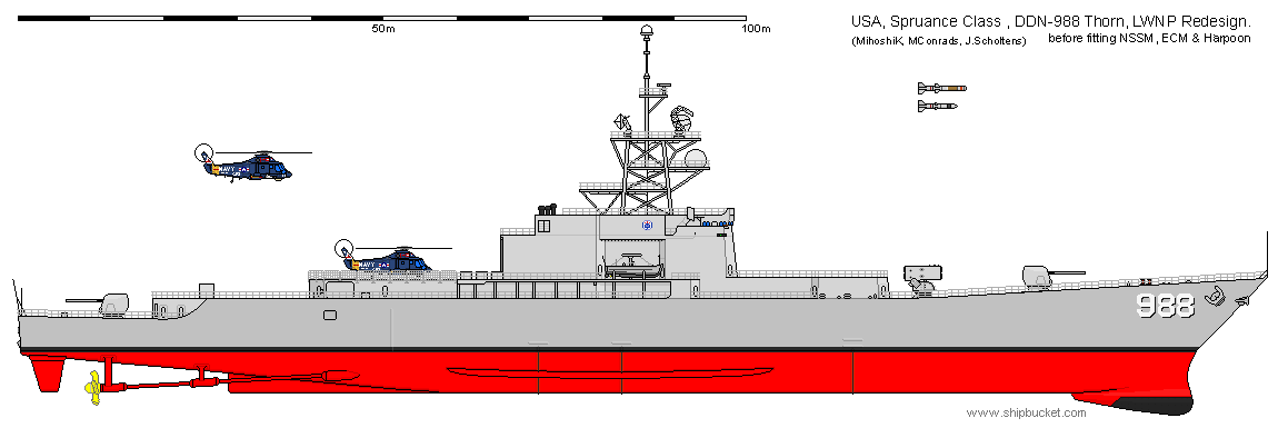
the superstructure and hangar are put more amidships, moving the helideck with it. to preserve strength, the lower level of the superstructure is partially kept in place, but the deck on top of this is available for weapons and systems.
the LWNP removal shafts are aft of the hangar and forward of the bridge. the midship gas turbine generators are moved towards the superstructure, as uptakes from the hull down would actually take more space then just putting it on top of the hangar. because of this, the hangar is of different shape too, and is actually symmetrical
the rest of the auxilary power unit is the same as on the regular spruance, as is the weapons fit and the modernisation plans shown below. all weapon positions but the phalanx and harpoon are as in the real world, as the phalanx and harpoons were placed on the superstructure in real life. thus, in the hull, nothing has changed but the removal of the generator sets now in the superstructure. this would keep the costs of this ship, if the powerplants are comparable in price, much lower then that of the real world DXGN, the virginia class. the growth space in the design would have been less though, and CGN-42 (aegis virginia) would be impossible.
the current superstructure is more compact in planform but has one additional deck compared to the spruance.
the only real drawback of this design in my opinion would be the lack of growth space (in the direction of tico) but that counts for all LWNP spruance designs, due to the lower GM, and the relatively compact mast, which would have interference problems faster then the original 2 mast setup.
design with optimised superstructure arrangement, with Mk 71
design with optimised superstructure arrangement, with ABL
design with optimised superstructure arrangement, modernised along the plans for the regular DX
design with optimised superstructure arrangement, AAW converted along the plans for the regular DX
the drawback of this design would be the powerplant itself. as was found out in my earlier studies on it, the safety limit on the reactor makes it impossible to run the unit at full speed for most of it's service life. due to this, the behaviour of the spruance class itself would actually not be that different with an LWNP ship, still operating at the same cruising and burst speeds for the same operational time. you would no longer have to refuel, indeed, so stratigical the ship has an advantage on the regular spruance, but an virginia DXGN would have a lot more use then an spruance DXGN on the battlefield. of course, the cost of an virginia is a lot more then that of an spruance for example. On value for money, the ships might thus end on about the same level. if this would be the case for regular DX vs DXN, that is something I cannot say for certain, and something we might never know for certain.
----------------------------------------------------------------------------------------------------------------------------------------------------------------------------------------------------------------------------------------
DG/AEGIS
ASMS, the system that became the present AEGIS was first conceived in 1963, when it became clear that Typhon would not lead to results. Development started slow, but in 1969 it became Aegis. The cost concentrated in the advanced fire control computers and radars, as in Typhon, but even more so in the Aegis system because it used the standard missile instead of a new developed missile.
In 1969 the only missile ship under development was DXGN, as DXG was dropped. Because of that, ASMS was designed to be fitted on a nuclear destroyer or cruiser of 10000 tons displacement. When Admiral Zumwalt became CNO, he was determined to increase the amount of combatant ships by designing low-cost ships, which was enforced by unit-cost and unit-displacement limits. DXGN of course did not fit in this plan: nuclear vessels were just too expensive to build in the numbers required.
Zumwalt wanted a low-cost Aegis vessel, and the limits were set as $ 100 million and 5000 tons. Of the 139 computer runs of the first series, only one design was within these limits
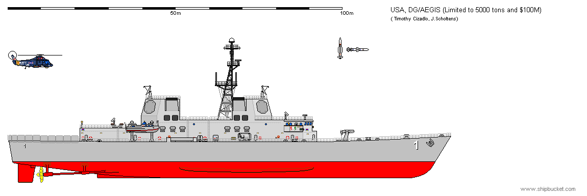
This vessel had just an Mk 22 launcher, a helideck and Aegis on board. This was considered too austere even for Zumwalt, so new limits were set.
These limits were set at $ 125 million and 6000 tons, which proved to be more realistic. Within these limits, the design considered varied considerably. At first it was to have an austere sonar suite and provision for landing a helicopter, but no hangar. The SPS-49 search radar was deleted. The launcher would have been the Mk 26 Mod 1, which allowed the ship to fire ASROC and Harpoon as well, next to the SM-2MR
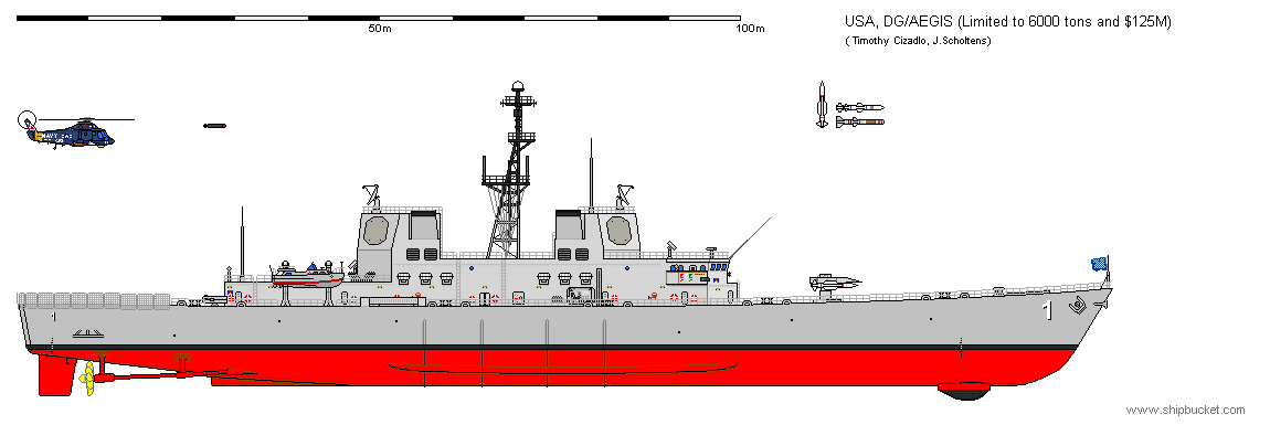
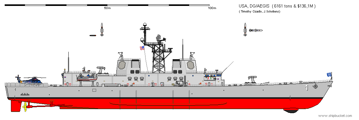
Critics argued that so valuable a ship should have at least 2 launchers. This resulted in a design with 2 Mk 13 launchers, which could not fire ASROC. LAMPS and SPS-49 were added, and this resulted in a vessel of 6161 tons and $ 136,1 million, both of which exceeded Zumwalts limits. This, and the lack of growth space in the Mk 13 launcher, made that this design was not satisfactory either, and a return to the Mk 26 was made, this time the Mod 2 with room for 64 missiles.
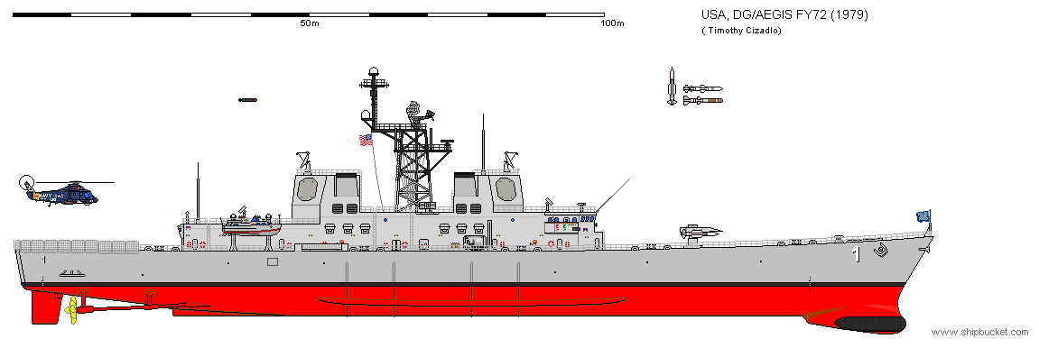
In the end, this resulted in the vessel shown underneath, the FY74 model, the only one about which exact dimensions are known.
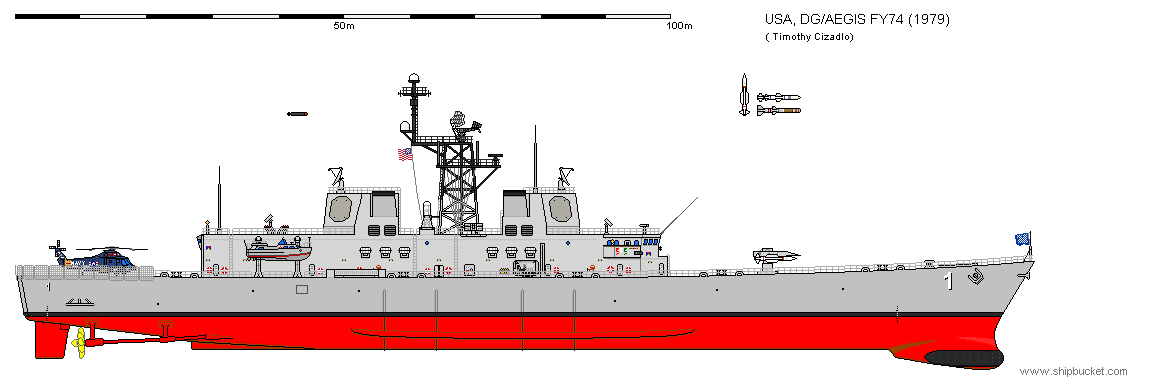
Displacement: 5884,3 tons
Length WL: 148,74
Beam: 16,15
Draft: 4,94
Power: 70000shp
Top speed: 29,4 knots
The cost of this variant rose though, and was not at $ 200 million. This would only get worse over time, but it was clear this was the minimal platform that could support the fleet with effective Aegis air defence.
However, within the navy there were still plans for nuclear ships, and it was considered if it would not be better to have only one class of first line combatants. This, in effect, was a return to the original ASMS/DXGN plan. The nuclear ships were too expensive to build in numbers though, so it was proposed to have 8 nuclear strike cruisers and 16 conventional powered DDG-47 class ships, based on the Spruance hull. In retrospect, this was a fortunate turn of events, as we can see on the resulting Ticonderoga class; it would not have been easy to put a combat system designed for 10000 tons on a 6000 ton hull.
----------------------------------------------------------------------------------------------------------------------------------------------------------------------------------------------------------------------------------------
Air Capable Spruances
In the late 1970’s the type A (Support/Multimission) and Type-B (Fighter) VTOL programs were still on-going. However, due to the sea control and vertical support ship programs dying out, there were no hulls to ship these VTOL’s. As such, the mission requirement for a small carrier still existed for the escort and air cover of small groups of ships (convoys and surface action groups), but no vessel was able to fulfil that requirement. The Type-B program was never really completed after the failure of the XFV-12, but for open ocean missions you don't need a dogfighter, you need an aircraft that can fly out and shoot down Tupolevs at long range. While this increased the number of missions that the Type-A airframe (At this point Grumman, Lockheed, and LTV were all proposing turbofan powered aircraft, while Bell-Boeing was showing off Tiltrotor technology, and would eventually win) would have to support, it didn't increase the size of the platform (anything that is flying several hundred nautical miles to launch Harpoons can do the same with Sparrows and AMRAAMs).
To create a platform for these VTOL aircraft, several yards suggested designs.
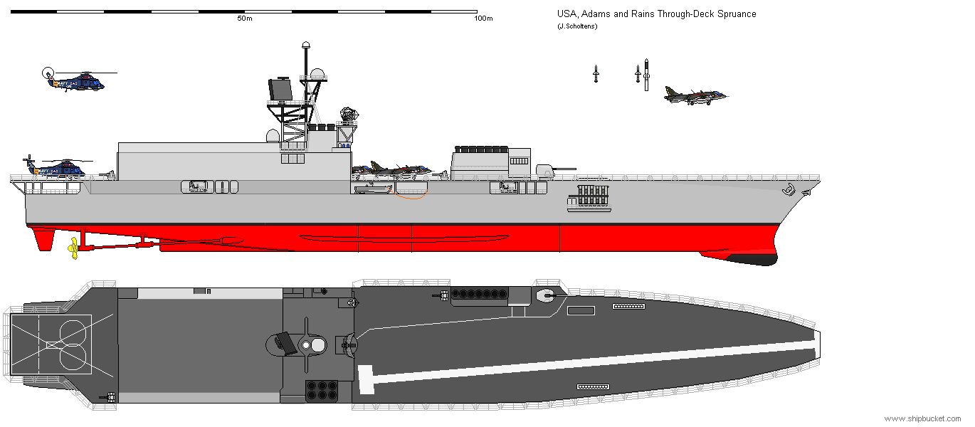
One of the earliest designs to appear was the work of Dean A Rains and Donald B Adams, both of Ingalls Shipbuilding Division. They proposed a design that on first glance had very little in common with the original Spruance class. The beam would be increased by the addition of sponsons, on top of which a full width superstructure would be build. This superstructure contained the aft in and uptakes (the forward ones were constructed in a separate, small structure forward), the bridge and a large hangar. Of the original superstructure, part seems to have found its way into the hull and part of it is in the sides and top level of the hangar. 2 custom batteries of a tactical length Mk 41 VLS was fitted forward and extended through the sides of the hull, to keep the flight deck clear. This vessel no longer resembles a Spruance class and can no longer do that role as well. What resulted here was truly a small carrier.
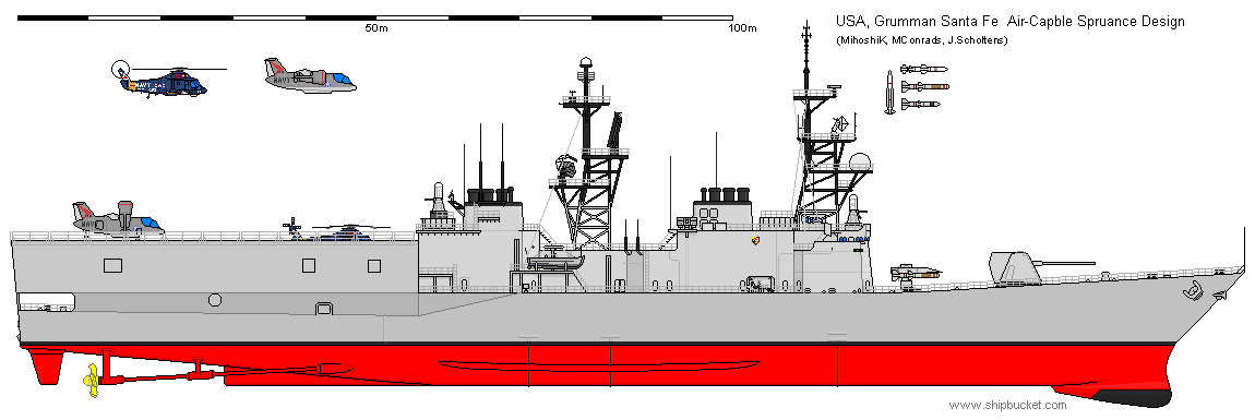
The below design was created by Grumman/Santa Fe Corporation. This design makes use of the modernisation scheme shown earlier, but replaces the equipment on the stern with a large hangar with a flight deck on top. Compared with the modernisation scheme, the ship lost Sea Sparrow and one of the guns and traded them for 2 additional phalanxes, secondary radar and as many as eight helicopters or four ASW VTOL aircraft. Due to the elevator required to bring the aircraft up from the hangar deck (on the main deck level) there was only one landing spot though. The great advantage of this design was the fact that on 9000 tons displacement and the original hull, she got both the capabilities of the regular Spruance and the ability to launch an air wing, large enough to be worth it.
In reaction on the proceedings article of October 1977 “Maintaining a Western Carrier Capability”, an article describing the abovementioned air capable Spruance class designs, Commander Ronald J. Ghiradella (USNR) suggested an alternative design to the USN. In his opinion the problem with the air capable destroyer designs was the mission definition. The mission for the design would have to be defined before any design concept is pursued.
According to the commander, the air capable DD-963 designs were ships in search of a mission, not capable to fill the destroyer role or be a satisfactory VTOL platform. None of the designs were still a good multi-mission system, as they were supposed to be.
To solve this issue, his design is slightly larger than the regular Spruance hull. He adds 40 feet (12,19m) forward of the machinery spaces. The goal of the design was to be both a capable weapons and aircraft platform. Adequate gunfire capabilities, including close in defence, were created by having an Mk 45 gun and 4 GAU-8 30mm guns (most likely EX-83 mountings) on each quarter. Forward of the bridge a missile launcher comparable to a harpoon system is fitted. An ASROC system could be substituted. The BPDMS system is mounted on the aft superstructure for close in air defence.
The in- and uptakes are both ducted to the starboard side, creating space for a hangar deck on the former main deck of the Spruance hull. On top of that an angled flight deck was to be fitted, with the purpose of larger aircraft payloads. The angled deck and superstructure are supported by sponsons with a total width of 66 feet (20,11m). The angled out funnels and the angled flight deck make the full beam to 87 feet (26,51m). The overall length of the vessel is now 606 feet (184,71m) with a flight deck of 470 feet (143,26m).
Aft of the superstructure an elevator is fitted (26 by 62 feet; 8,0 by 18,9m) which services the 2 hanger deck levels: one on the former main deck level and one slightly lower, between the elevator and the stern. The ship would support 12 medium sized helicopters or 8 helicopters and 4 harrier type aircraft. In the opinion of the commander, this would result in a vessel serving both the aviation and weapon platform roles satisfactory.
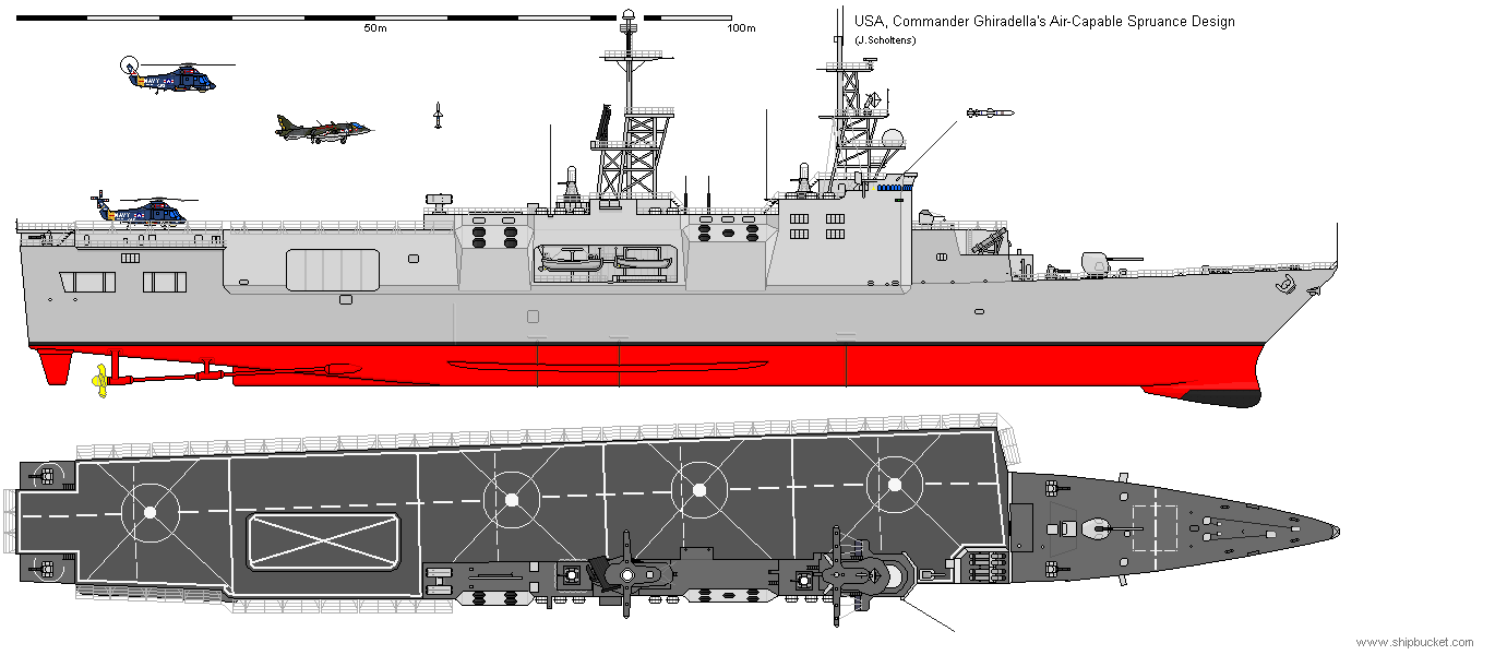
Looking back after drawing this vessel some errors come in sight. The air intakes for the cooling of the exhausts are above the uptakes, therefore being unable to cool any of the exhaust and better left off. The UNREP gear goes straight over the exhausts and the GAU-8 seems to have no dedicated fire control system, nor does the sea sparrow. The ship is a bit on the crazy side, but not much more so than many of the flight deck Spruance designs of earlier date.
Below I have included a drawing correcting the most glaring errors. The variant shown should actually be capable of being operational, while still true to the original design. There are still some problems with the design, but I chose not to correct those as that would be own design territory.
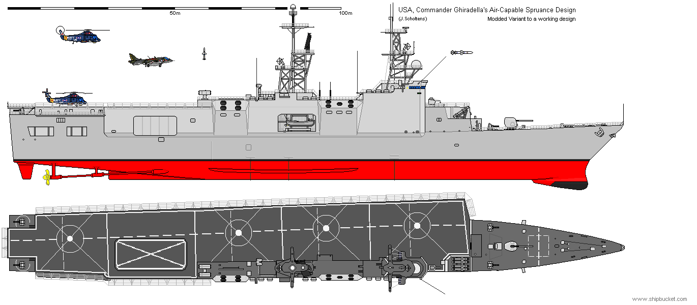
I fixed the boat bay (it went through the air intakes of the aft engine rooms) by moving one of the boats to the other side of the ship. The same goes for the forward air intakes: that engine room is on the other side of the ship and the air intakes were below the flight deck level so it would save space putting them at the other side of the vessel. The exhaust cooling intakes are now in the correct position under the uptakes, which I used to make the uptakes slightly higher. The elevator is now big enough for the AV-8B which would be in service at about the same time as this vessel. In addition, the SPS-48 is now in the same position as it would be on the regular Spruances. This allowed me to fit an SPG-60 aft to serve as guidance channel for the EX-83 mountings, allowing them to fulfil the CIWS role (the phalanxes, not listed in the textual description, are thus removed) an Mk 95 is added for the sea sparrow guidance, as on the Spruance.
Only one air capable Spruance was ever ordered, DD-997 Hayler. This vessel is mentioned above this section in the section: DD 963 Spruance Class: never build designs. This vessel was an only slightly modified vessel, fitted to take 4 SH-2 or 2 SH-3, double the amount of the basic Spruance class ships. This vessel was however not build to that specification, as the redesign cost was not justified for only a single ship with only marginally different capabilities compared to the rest of the class. The Hayler as build thus differed only in some details from the rest of the class.
----------------------------------------------------------------------------------------------------------------------------------------------------------------------------------------------------------------------------------------
DGV - Destroyer, Guided missile, Vertical take-off aircraft
In 1980 there was work done, by Boeing, Lockheed and Grumman, for the use of 'turbofan VTOL aircraft' for both offensive and defensive measures for the fleet. The aircraft resulting would have been the Grumman design 698 VTOL aircraft.
this aircraft was designed to be able to be used by the ships then in commission, such as the Perry, Spruance and the Hayler DDH design (which at that point was being build, but to the regular Spruance design) but the full potential of the aircraft would be reached with an special build ship. That ship would have been the DGV.
The ability of this ship was to give fleets which operated independently from carrier battle groups part of the capabilities of the carrier battle group.
Versions of the Grumman design 698 would operate as a surveillance/misseleer aircraft, jammer aircraft, and possibly also ASW aircraft. This would give amphibious groups or merchant escort groups a much longer range against any target then regular escort ships could do.
The DGV was designed in collaboration between Litton-Ingalls and Grumman. The design was based on a Spruance hull, lengthened slightly for the installation of an active stabilization system. This made air operations easier. Under the waterline, little else changed from the Spruance to the DGV hull.
Above it, everything was changed though. The superstructure was moved to the side, and to the side of it a hangar was build. Landing platforms were added aft, while the bow was filled with a takeoff ramp. At the fore and aft ends of the hangar, offset to the sides, were 2*64 cells VLS.
Interesting to see is that the DGV was more than a carrier for these aircraft. The ship carried its own load of Mk 41 VLS cells, allowing the aircraft to be a guidance unit for standard missiles, tomahawks and ASROC class weapons. apart from an takeoff run which allowed the aircraft to take more stores into the air (such as 2 harpoon anti-ship missiles, a pair of long range air to air missiles (undefined), up to 6 AMRAAM class weapons or 4 lightweight torpedoes) the ship carried its own load of Mk 41 VLS cells, allowing the aircraft to be an guidance unit for standard missiles, tomahawks and ASROC class weapons.
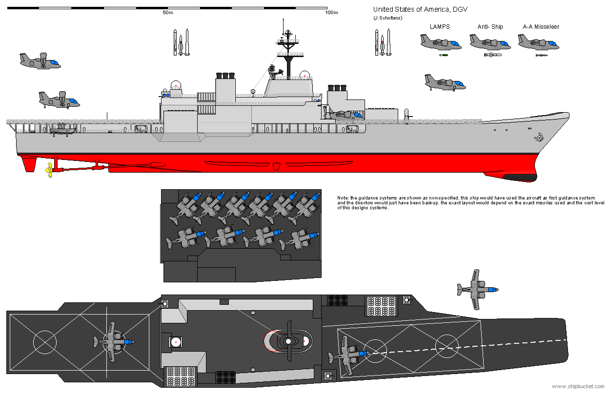
Some specs:
Displacement - 12000 tons
Length - 162,2m WL; 173,6m OA
Beam - 20,7 WL; 28,6m OA
Draft - 10,4m
The hangar could take 8 surveillance/missileer aircraft and 2 jammer aircraft.
The propulsion unit would have been as Spruance, 4 LM2500 gas turbines, COGAG, resulting in a top speed of more than 29 knots.
Interesting to see is that this design originated from later then the flight deck Spruance designs, and while its origins are the same the end result is somewhat different from the others.
----------------------------------------------------------------------------------------------------------------------------------------------------------------------------------------------------------------------------------------
I look forward to your comments, be them good or bad. Detailing might be off or incomplete, as I will revisit all never builds I have WIP after all real spruances are done (for perfect accuracy) these will be modified, checked and completed when I get that far.
Thank you for reading, and I will post notifications when I update this first post in the thread below.


